

So many wires . . . So many colors . . . And, so many kinds of trailer wiring connectors. Yikes! Where do I start? I need a trailer wiring diagram! And, a little more information to make sure I get all the wires right!
There are several standards for trailer wires, and if you search, you will find a different Trailer Wiring Diagram for each. The standards have a purpose, so there is no reason for kooky wiring that won’t work with other tow vehicles.
The right wiring depends on your electrical needs. To start, every trailer needs lights – brake lights, turn signals, and tail lights. Most need side markers / running lights. Some have electric brakes, and some need auxiliary power for interior lights, etc..
The trailer wiring diagram(s) and explanations are a cross between an electrical schematic and wiring on a trailer. Then, below, there are notes for wire sizes and functions.
In this article we cover the 4-Pin Flat connector, the 5-Pin Flat connector, and the 7-Pin Blade connector with colors of the SAE ( J2863 ) aka “Traditional” Standard. This is the most common, and most consistent standard. If you have the RV Standard ( RVIA/NFPA, for 7-Pin only), the connections are the same, but some colors are different. That means both wiring schemes will plug into the same tow vehicle and function just fine.
Other styles also exist – including industrial and military standards – with various styles of 4, 5, 6, 7, 8 pin connectors – and different wire arrangements. It can get confusing, so they are beyond our scope here. If you don’t already have a specific standard in mind, follow the trailer wiring diagram below.
At a minimum, all trailers need at least 4 functions: Tail lights, Brake lights, Left & Right signals. 4 wires will give these functions, so the simplest scheme is a 4 wire, 4-pin connector.

The most common 4 wire connection is this traditional 4-Pin Flat Connector. Trailers for this are usually fairly light weight and don’t have brakes or other power accessories. For example, small utility trailers, light boat trailers, little campers, off-road trailers and many more will use this 4-Pin Flat connector.
Lighter Duty Trailer (No Brakes) = Use a 4-Pin Connector.
1. White = Ground (See White Wire Notes below.)
2. Brown = Tail Lights, Side Markers and Running Lights (See Brown Wire Notes below.)
3. Yellow = Left Turn Signal & Left Brake Light
4. Green = Right Turn Signal & Right Brake Light
Please see the Trailer Wiring Diagram / Connector Application Chart below. The 4-Pin connector only has the first 4 items listed, then can ignore the other wires of the trailer wiring diagram.
This 5-pin is similar to the 4-pin above, but not as common. Typically, the 5th wire (blue) is for Electric Trailer Brakes , but not always. Sometimes it is used for backup lights, or to interact with surge brakes, so be careful. The 5th pin is not as standard as the first 4.

Trailers with capacity over 3000# Total Gross Trailer Weight should have brakes. That is not mandatory everywhere, but it is definitely a good idea. If a trailer has brakes, then it needs a connector with at least 5 wires.
Traditional Trailer + Brakes = Use a 5-Pin Connector.
1-4 Wire the first 4 pins (White, Brown, Yellow, Green) just like the 4-pin connector above.
5. Blue = Electric Brakes, or other uses. (See Blue Wire Notes below.)
In the Trailer Wiring Diagram / Connector Application Chart below, use the first 5 wires, then ignore the rest.
While the most common use of the blue wire is for electric brakes, the 5th pin is sometimes used to disable hydraulic surge brakes (in reverse), or for backup lights. Check it before connecting one.
Note: If your vehicle has a built-in 7-pin socket, but you only need 5 pins, then use a 7-pin connector anyway (see below), and leave out the last 2 wires. It accomplishes the same thing for 5 wires using a connector that is already compatible with your vehicle. It is perfectly fine to leave some pins vacant.
For trailers that have a little more going on electrically, we recommend 7-pin connectors. The 2 added pins are typically for Auxiliary Power and Back-up Lights.

Expanded Use Trailer + with Brakes, Aux Power and/or Back-up Lights = 7-Pin Connector.
1-4 Wire the first 4 pins just like above.
5. Blue = Electric Brakes, or other uses. (See Blue Wire Notes below.)
6. Red (or Black) = 12V Auxiliary Power. (See Red Wire Notes below.)
7. Purple (or Gray) = Back-up Lights. (Sometimes another color.)
7-Pin Connectors (with blades) like the one pictured are very common for RV’s and other bigger-ish trailers. This is the style we recommend.
It is OK to leave a pin or two blank (unused and unconnected). For instance, looking at the trailer wiring diagram, if you want Auxiliary Power, but don’t have back-up lights, then just leave the purple wire out. A blank spot (unconnected pin) does not hurt anything.
Colors in this article follow the SAE Standard. BUT, for the 7-pin connector, there is also an RV Wiring Standard. Weird, because the connections are the same, they just scramble the colors. Don’t worry about the exact colors. The important thing is the connections, not the colors.
| SAE Trailer Wire Color Codes – Colors Coordinate With Trailer Wiring Diagram | ||||||
|---|---|---|---|---|---|---|
| Connector Style | Pin | Function | Color | Description | ||
| 7-Pin | 5-Pin | 4-Pin | 1 | Ground | White | Ground for all electrical functions |
| 2 | Tail Lamps Running Lights Side Markers | Brown | Power for normally ON lamps Tail, Running & Side Markers | |||
| 3 | Left Brake Light Left Turn Signal | Yellow | Multi-function signal for the Left Side Rear Tail Lamp | |||
| 4 | Right Brake Light Right Turn Signal | Green | Multi-function signal for the Right Side Rear Tail Lamp | |||
| 5 | Brake | Blue | Electric Brakes Control or some other uses (5-Pin only) | |||
| 6 | Battery | Red (or Black) | Vehicle Power +12V Battery Charging and Accessories | |||
| 7 | Reverse Lights | Purple (or Gray) | Reverse Lamps / Hydraulic Brake Disengage | |||
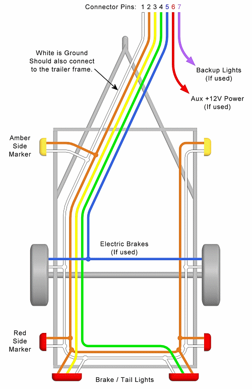
Single Axle Trailer Wiring

Tandem Axle Trailer Wiring
The 2 above trailer wiring diagrams fit the needs of most trailers. The first image shows a single axle trailer, and the second, wiring for Tandem Axles. Only the (blue) brake and (white) ground wires have more connections for the tandem. Then, you can expand the same conditions also for triple axles.
Use only the needed wires, and ignore the others. For example, if you have a 4-Pin connector, just ignore the Blue, Red, and Purple wires. Or, if you don’t need Auxiliary Power, just leave it out. Perhaps the axles do not have brakes, then no need for that. Don’t change pin numbers or wire positions if a function is not used – just leave the pin blank (not connected).
The above trailer wire diagrams don’t show the triple set of marker lights central on the front and back. Some trailers need them, and some do not. Usually this has to do with trailer width. Check local ordinances for requirements.

If needed, the 3 center marker lights are located central on the back, maybe low (on the bumper) and/or high (for an enclosed trailer), and maybe high on the front. Check legal requirements to see if they are required in your country or jurisdiction.
For trailers in the USA: Typically a red 3 light set is required on the back, if the trailer is 80″ or wider – or – if over 10,000 lbs GTWR. Also, near the top in the back if taller than a certain amount. An amber 3 light set is required near the top in the front, if taller than a certain amount (usually some amount over the height of the tow vehicle). Again, check regional requirements.
Typically the 3 center marker lights are at a high point on the trailer – like above the back doors for an enclosed cargo trailer. They are fine on the back bumper of a flatbed trailer, even when the load is much higher. There are lots of extras in the laws (like top corner markings), so find out what you need for your specific trailer.
If you need the more marker lights, connect them on the Brown and White wires just like the side marker lights. (See the partial trailer wiring diagram.) These do not require additional connections at the hitch, just more wiring within the trailer. These lights should be ‘ON’ basically all the time.
In addition to the three center marker lights, most trailers over 80″ width require reflectors or reflective tape in alternating red and white on the sides and back. There are a lot of regulations here for height, and GVWR, especially when trailers are longer than 20′. I am not sure about requirements outside of the USA.
Check your local jurisdiction so you can mark and light your trailer properly. Reflectors and reflector types change by jurisdiction. To some, this is overkill, but even if it is, making it right can save you a ton of legal hassle and trouble.

Many trailers are required to have a Breakaway System on board. Basically, this is a way of applying the trailer brakes if the trailer comes disconnected from the tow vehicle. In many parts of the USA, trailers over 3000 lbs GVWR need a breakaway kit, so check your local laws.
If you have electric brakes (or electric over hydraulic or some others), then it will involve the trailer wiring. Here is a partial wiring diagram to include your trailer breakaway system. Since there is a lot to discuss, we have an entire article about breakaway kits with lots more information. In the meantime, use this diagram to guide the wiring of the system. Superimpose this on the images above to see how it all comes together.
The breakaway system usually resides in, on, or under the front part of the trailer. The pin pull switch is near the hitch. The system hooks into the electrical system by connecting Auxiliary Power (Red wire +12 VDC) to keep the battery charged, the Brakes (Blue wire) to actuate the brakes, and Ground (White wire) to complete the circuit. Again, please see the article about breakaway systems for a lot more information.
Where do the wires go? Now that we have the trailer wiring diagram and some definition for connectors, where do the wires actually go?
Nestle the wires into and around the frame where practical for protection. We do recommend protecting the wires with a covering of some sort. The cover is not in the trailer wiring diagram, but flexible conduit, plastic conduit, or other approaches are great. A covering does not need to be watertight, but do consider weather protection when splicing into the wires. For tips on wiring, splicing, routing and protecting, see our post on trailer lights and wires. See more in the Wire Routing Notes below.
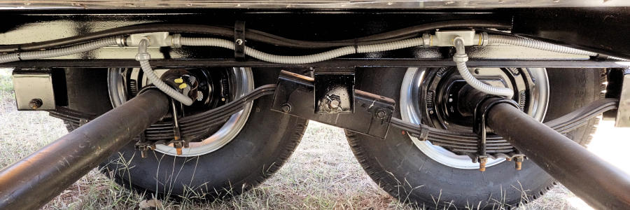
This photo shows an ideal way to handle trailer wires. While the flexible sealed conduit nestles in and secures to the frame, it protects the wires from snags and from weather. Great job on this one.
Many different sizes of wires are available. Typically wire sizes are list by “Gauge” – often designated AWG (meaning American Wire Gauge) – which is a measure of the metal diameter in the wire. The numbers are a little backward because a smaller number is a thicker wire. So, a 12 gauge wire is bigger than a 16 gauge wire. See this chart for AWG dimensions.
There is some rhyme to it. For trivia, 10 AWG wire is 10 times the cross section area of a 20 AWG wire. Also worth noting, in the ranges we need for trailers, the wires are only in even increments, like 16, 14, 12, 10 gauge.
There are 3 things that dictate the wire size needed:
Every device will have a specification for current, so add them all up for a total for each wire. For example add up the current requirement for all the running lights to know the current required for that wire.
Using Trailer Brakes for an example, according to this published chart, a 14 Gauge Wire (AWG) at 5 Amps is good for 18.4 ft. However, at 10 Amps it is only good for 9.2 ft.
We recommend 16 gauge and larger for low power lighting, like LED’s. Then, for power hungry things like brakes, use a thicker wire size, like 14 gauge or 12 gauge. Same for Auxiliary Power. Please see the wires by function below (listed by wire color). If the trailer is long, go up one size on the wire gauge.
We recommend sealed and submersible LED lights for just about everything. Yeah, most trailers are never submersed, but almost all get very wet like in heavy rain or when washing. Pay the extra dollar or two and get the higher quality lights. Trouble free operation with higher quality lights make them worth it.
Lighting circuits with low power lights like LED’s have low power requirements, so even with a lot of lights, they don’t use much power. For lights, a relatively small wire gauge works. We recommend 16 gauge and larger, not so much because of the power requirements, but because the wires are stronger, more robust, and have more surface area for splice connections. It is worth the small additional expense.
The “Ground” or “Negative” wire connects to the vehicle battery “minus” side. White Wire above. The trailer wiring diagram shows this wire going to all the lights and brakes. Also, it must connect with things (if included) that use the Aux Power and Back-up lights too.
Some trailer builders just connect this wire to the trailer frame, then connect the ground from all the other lights and accessories to the frame as well. While this usually works, the ground portion of the circuit is often the root of trailer electrical problems. To avoid some of those issues we recommend running the white wire with all the others and connecting the ground from each light directly to the White. It is a little more work, but it can save big headaches later.
We also recommend connecting the white wire directly to the trailer frame (in addition). If this sounds redundant, you probably have not experienced the frustration of trying to find problems that ultimately come down to weirdness with a floating ground, or static charge, or rusty frame connection. Skimp on the ground wire at your own risk.
Size: This wire should be at least as big as the largest wire in your harness. If only lights are in the circuit, and the lights are LED (low power), then a small ground wire is acceptable. However, if you have electric brakes or auxiliary power, this wire must be larger.
The Brown Wire goes to the lights that are always ON as you travel. These are the running lights, the low intensity portion of the tail lights, side markers, and corner markers. Also, if used, the sets of 3 lights central in front and back of the trailer. See the above partial trailer wiring diagram showing the 3 marker lights. All of these are on the Running Lights wire.
While the typical sets of 3 lights central in the trailer are not in the main trailer wiring diagram above, they are important in some situations. They are not normal for smallish DIY utility type trailers. However, if you need them or want them, the brown wire feeds them too (and the white for ground). Check local laws for requirements on which lights your trailer needs.
Tiny Houses may or may not need the 3 lights, but again, check local laws.
Size: The Brown wire only feeds power to lights, so size it for the power requirements of your lights. For a utility trailer, that is probably not much power, so a smaller gauge is OK. For a large enclosed trailer with lots of running lights, consider a larger wire gauge.
The two wires, Yellow and Green, handle double duty for function. They activate lights for both Turn Signals and for Brakes. It is the same physical “light” at the rear of the trailer, but it serves 2 functions. The wiring in the vehicle sorts out how those signals are sent.
The Yellow wire handles the Left side – left as you look at the back of the trailer. (Or, in a different way of thinking, left as you are sitting in the driver’s seat of the tow vehicle.) The Green wire handles the Right side. See the above trailer wiring diagram for a visual.
Size: See the above discussion about Wire Size. We recommend 16 gauge and larger for lights, and we recommend LED lights.
Typically, the blue wire is for electric trailer brakes, however, this wire is not as standard as lights and ground.
For electric brakes, on the vehicle side the blue wire goes to the brake controller. Many styles of brake controllers are available, so find one that works for your vehicle. On the trailer side, the blue wire goes to the brakes and breakaway circuit. (See the trailer wiring & breakaway diagrams above.)
Here are some other ways the blue wire is sometimes used.
Just be careful when using a 5-pin connector. Make sure the car wires match functions of the trailer.
To solve some compatibility issues with my trailer for tow vehicle wiring – like when a friend wants to borrow it – I simply made a short adapter wire. The adapter connects the 5-pin on my trailer to a 4-pin connector that goes to the tow vehicle. Of course that means the trailer goes without brakes. It works because the trailer is not big or heavy – and with a light load it does not require brakes. I just tell the borrower the load capacity is 3000# (even though true capacity is 5000#.)
Going the other way, it is easy to use an adapter that goes from the trailer 5-pin to a standard 7-pin (with 2 wires left blank). That way the trailer brakes work when the tow vehicle has a 7-pin connector.
Size: Don’t skimp on wire size for your brakes. For a single axle, 14 gauge is good, but for tandem axles, use 12 gauge wire. For a long trailer and for triple axles, use 10 gauge wire.
The pin for Aux Power is usually with a Red Wire, but sometimes it is different like Black. Sometimes we call it ‘Aux Power’ or ‘Auxiliary Power’ or ‘Accessory Power’ or ‘Batt 12V+’. Whatever the name it connects to the tow vehicle positive, DC power. Typically, auxiliary power is for charging the Breakaway battery, RV batteries, interior lights, power for accessories, etc.
The extent of routing for the Red wire is not on the above Trailer Wiring Diagram because it is optional, and often different for each trailer. In the Breakaway wiring section, the schematic there shows how the Breakaway battery box connects to the Red. That maintains the battery charge.
If you don’t need separate power on the trailer, just leave that pin out. If you do use it, then be sure you protect the vehicle electric system from shorts (use a fuse or circuit breaker). Also, it is good to protect the system from completely draining the tow vehicle battery. (Like if you leave an interior light on, then come back and find your vehicle battery dead.)
Size: Use a wire size appropriate for the power demands. If it is just for charging the breakaway battery, then 16 gauge is fine. If you are powering up more batteries or lights in the trailer, then use 14 gauge or even 12 gauge. Don’t overload this wire. If you do need large amounts of auxiliary power, consider a battery pack on the trailer, or use a generator, or install special larger gauge wiring from the vehicle alternator.
As in the trailer wiring diagram above, the the purple wire is for back-up lights, and/or for disengaging the surge brakes when the trailer backs up. This wire is not always Purple. Often it is Gray, or Black. But the color does not matter if it is connected correctly.
Actually, in many applications this wire is left off. Some trailers have back-up lights, most do not. It is convenient to have the lights to tell people behind that you are backing up, but they certainly don’t provide any visibility for the tow vehicle driver. (I think that is why they are often left off.)
Size: See the above discussion about Wire Size. We recommend 16 gauge if it powers only the back-up lights. If this wire is for disabling the surge brakes, then consult the product requirements to determine how much electrical power, and the necessary wire size.
The trailer wiring diagram above gives one flavor for routing direction – starting at the tongue connector, then wrapping around the trailer. Other people suggest splitting the wires near the tongue, then routing down both sides – Right and Left specific. Either approach is fine.
While wire routing is a personal preference, I often like the wrap around approach a little more because it makes a ‘trunk’ that distributes power as it goes. It also keeps the wires all in one group as they traverse along the tongue so they are easier to protect. The amount of wire is almost identical for both the split and wrap around approach.
On the other hand, for a long trailer, the split approach has good merit due to the length of the wires. As above, length is a factor in choosing wire gauge, so with a long trailer that is certainly worth considering.
Hollow frame members are often the route for wires. For instance, if the frame is constructed of rectangular steel tube, then putting wires down the tube seems like an easy way to protect them. While this is true, it also means that you can’t cap (seal) the ends of the tube to keep moisture out. That is a trade-off to consider, but it does not have to be all or nothing. On my last trailer, I routed the wires through the tongue tube, then outside the main frame members (tubes) so they can seal. Wire and light connections are outside of the frame tubes under the trailer bed.
When running wires consider the possibility of changes down the road. If you are sure changes will never happen, button things up super tight. If you think changes might happen later, then leave access to the wires. For example, for a little camper, you might think Aux Power is on the “I am never going to use that” list. But in a few years, you might find the solar does not always cut it, and Aux Power is suddenly desirable. By leaving access to the wire routing, running the additional wire is not so difficult. Food for thought.
Finally, consider where and how you protect the lights. I have seen many damaged trailer lights. It is easy to do. So, when you make the trailer, build in some protection. In our trailer plans, we like to place lights in protected areas, or add protection around them. That said, lights do get broken, so make them accessible to change if that time comes.
Another source with a trailer wiring diagram comparing connectors is etrailer.com I also like the complete connector discussion at Curt Manufacturing. You can get trailer electrical items at any trailer parts store, or online. etrailer and JohnsonTrailerParts.com are both good sources.